
Collector System & Interconnection
Collector network and generator interconnection design for wind and solar plants — from array cabling to the point of interconnection.
Connecting generation to the grid
NEWATT designs the medium-voltage collector network that gathers power from wind turbines or PV inverters and the interconnection that delivers it to the grid.
We optimise cabling, losses and reactive power, and design the interface to the substation and point of interconnection for a compliant grid connection.

What this involves
In a wind or solar plant the collector system is the network that gathers power from every turbine or inverter and delivers it to the grid, and its design drives both losses and cost. NEWATT designs the medium-voltage collector network and the interconnection that connects the plant to the wider system.
We design the array and string cabling, group it into MV feeders, and optimise the layout for losses, reactive power and cable cost. At the grid end we design the point of interconnection, the interface to the collector or step-up substation, and the metering and protection needed to satisfy the connection agreement.
The outcome is a collector and interconnection design that is efficient, compliant and coordinated with the rest of the plant — minimising energy losses over the life of the asset while meeting the network operator's connection and metering requirements.
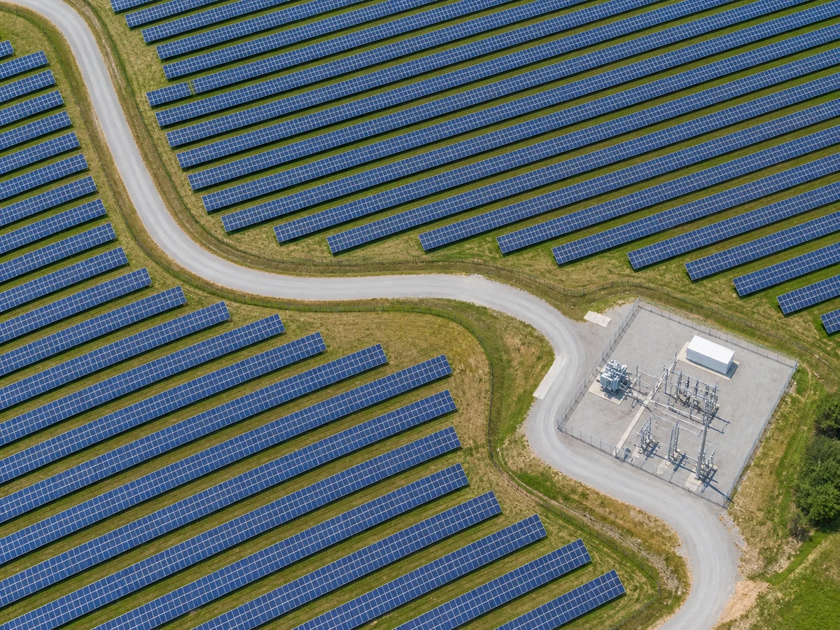
The collector network
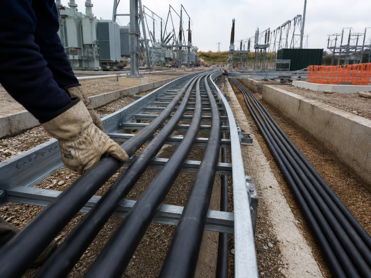
Array & string cabling
DC or AC array cabling is sized for the string and combiner-level currents specific to the plant layout, accounting for voltage drop over long cable runs and the derating that comes with tray, duct or direct-buried installation. We prepare cable and combiner schedules that tie every string back to its inverter or combiner box, so installation teams have an unambiguous record of every run. Routing is checked against the civil layout to keep cable lengths — and losses — to a minimum.

MV collector feeders
The MV collector network that gathers power from inverters or turbines back to the substation is sized for thermal capacity, voltage drop and fault withstand across the whole feeder length, not just at the terminals. We design the feeder topology — radial or looped — size conductors for the actual load profile, and prepare cable schedules and routing drawings that coordinate with trenching and civil works. Feeder protection settings are cross-checked against the cable withstand ratings before issue.
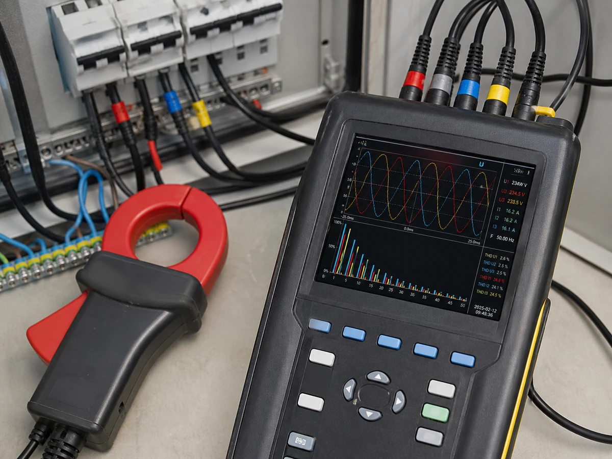
Reactive power & losses
We model reactive power flow and system losses across the collector network to confirm the plant meets grid-code power factor and voltage requirements at the point of interconnection under the full range of operating conditions. Loss calculations cover cable, transformer and switchgear losses, feeding into the energy yield assessment so the plant's net output reflects real collector-system performance. Where compensation is needed, we size capacitor banks or specify inverter reactive power capability to close the gap.
Cable sizing & ampacity
Every collector cable is sized against continuous ampacity, short-circuit withstand and voltage drop limits, using the installation method, grouping and soil or ambient temperature that actually apply on site rather than generic assumptions. We apply derating factors from the relevant IEC or IEEE ampacity tables and check the result against both steady-state and fault conditions. Sizing calculations and cable schedules are issued together so the basis for every cable size is fully traceable and auditable.
Grid interconnection
Point of interconnection
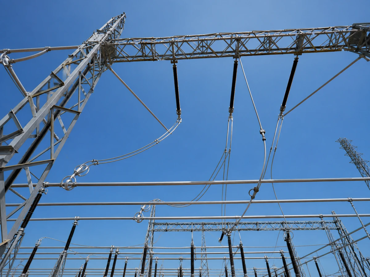
We define the point of interconnection with the utility or grid operator, establishing voltage level, fault level, metering point and the technical requirements the plant must meet at that boundary. This includes coordinating single-line diagrams, protection philosophy and communication requirements between the plant and the utility substation. Getting the POI definition right early avoids costly rework later, since it drives switchgear ratings, protection settings and the interconnection agreement itself.
Grid connection studies
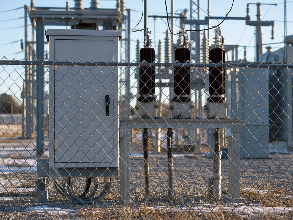
Grid connection studies demonstrate the plant meets the utility's technical requirements — voltage ride-through, frequency response, power quality and reactive power capability — before energisation is approved. We prepare load flow, short-circuit and stability studies specific to the interconnection point, along with the compliance documentation utilities require as part of the connection agreement process. Studies are structured to answer the utility's actual questions, not just to satisfy a generic checklist.
Substation interface
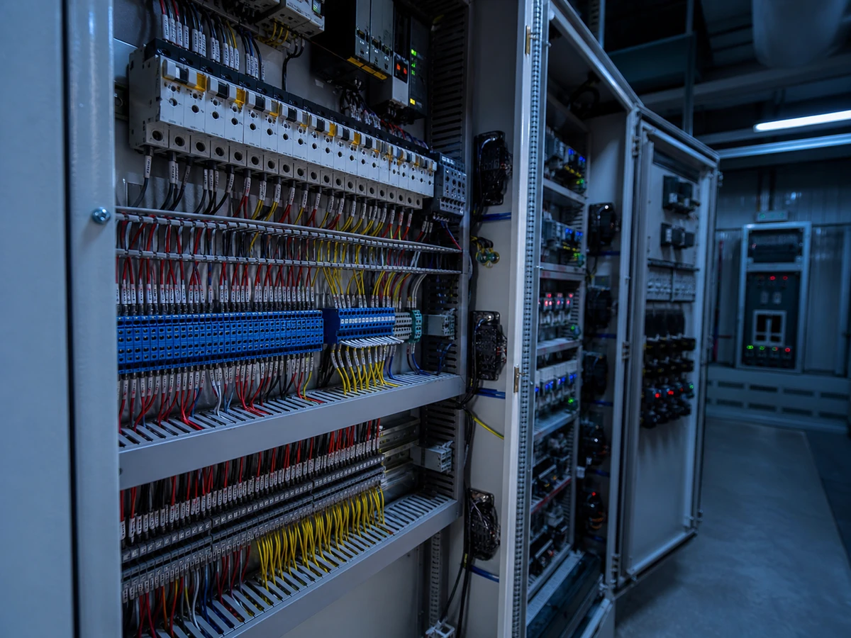
The interface between the plant's collector system and the interconnecting substation is designed so protection, metering and control signals hand over cleanly between the two systems, with no ambiguity about which party's equipment is responsible for what. We prepare interface schedules, protection coordination across the boundary and control philosophy documents that both the plant operator and the utility can sign off against. This keeps the interconnection agreement grounded in a design that's actually been engineered, not assumed.
Metering & compliance
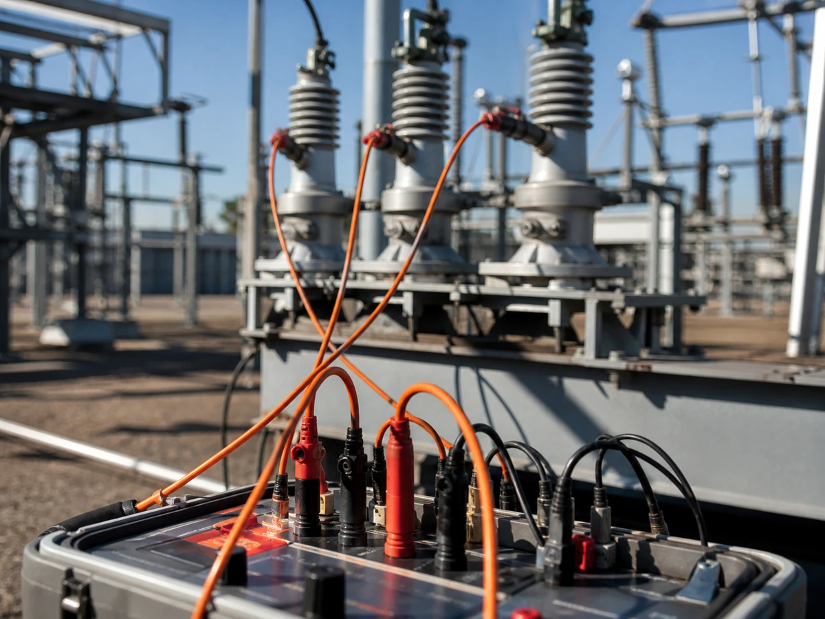
Revenue metering at the point of interconnection is specified to utility accuracy and CT/PT ratio requirements, with metering schedules and wiring diagrams prepared to the standard the grid operator expects. We track the compliance documentation the interconnection process requires — test certificates, type approvals and study reports — so nothing holds up energisation at the last stage. Where the utility requires witnessed testing, we prepare the test procedures and support the site team through it.
Have a scope in this area?
Share your requirements and we'll respond with a defined scope, programme and fixed fee — typically within two working days.
Request a proposal