
Earthing & Lightning Protection
Earthing-grid and lightning-protection design for safety and compliance — with soil modelling and step / touch analysis.
A safe, compliant earthing system
NEWATT designs earthing systems and lightning protection for substations, plants and buildings — engineered for personnel safety and equipment protection.
We model soil resistivity, design the earth grid, and verify step and touch potentials against the governing standards.
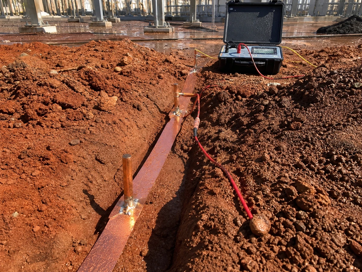
What this involves
Earthing and lightning protection are what keep people and equipment safe, so they are engineered rather than assumed. NEWATT designs earthing systems and lightning protection for substations, plants and buildings, verified against the governing safety standards.
Starting from measured soil resistivity, we model the ground with a multi-layer soil model, design the earth grid and rods, and verify step and touch potentials against IEEE 80 and IEC limits using CDEGS. Where the site is difficult, we optimise the grid rather than simply adding copper.
For lightning we carry out a risk assessment to IEC 62305, design the air-termination and down-conductor system on a rolling-sphere basis, and coordinate surge-protective devices to protect sensitive equipment. The deliverable is a complete earthing and lightning design with the calculations and drawings that demonstrate safety and compliance.
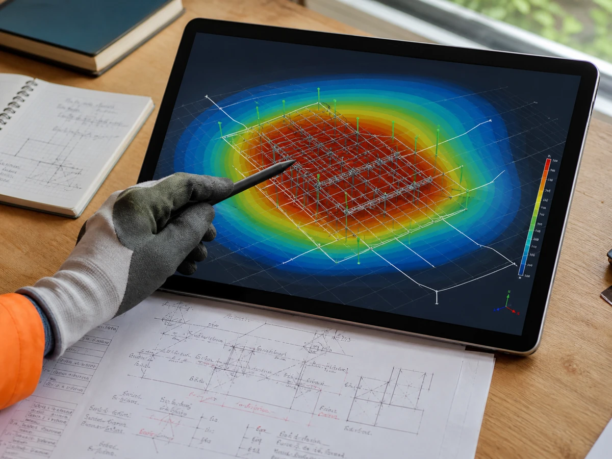
Earthing system design
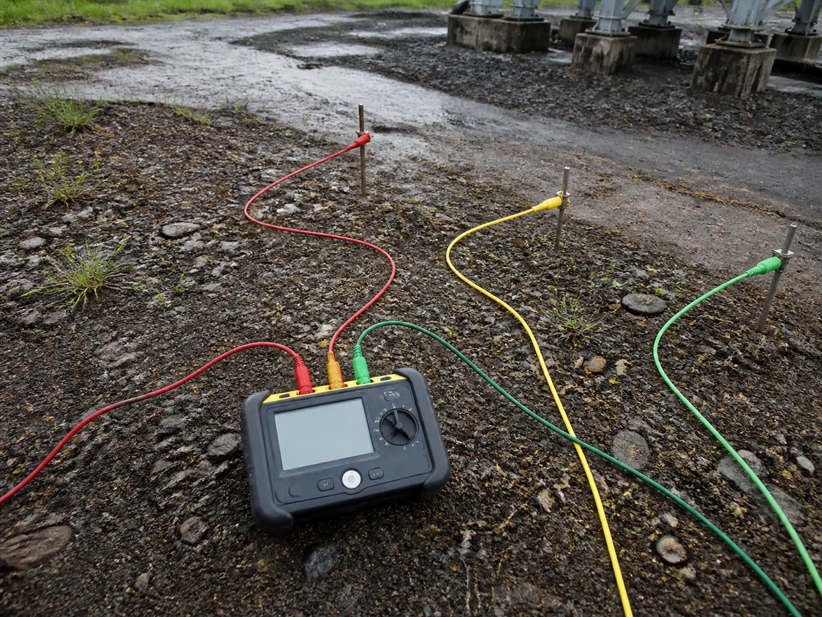
Earth grid design
We size the earth grid — conductor cross-section, mesh spacing and electrode arrangement — from fault current magnitude, duration and the site's soil resistivity profile, rather than a standard grid size applied regardless of conditions. Grid layout is developed alongside the equipment general arrangement so conductors run under the equipment they're protecting, and connections to structures, fences and cable armouring are shown explicitly. Earthing drawings are issued with conductor schedules ready for site installation.
Soil resistivity & modelling
Soil resistivity data from site testing — typically Wenner four-pin measurements — is used to build a layered soil model that drives every subsequent earthing calculation, since a uniform-soil assumption can significantly under- or over-state real grid performance. We interpret resistivity survey results, build the soil model, and use it as the basis for grid resistance and potential-rise calculations. Where site data isn't available yet, we specify the testing programme needed before design can proceed reliably.
Step & touch potential
Step and touch potentials are calculated at every point across the site an operator or member of the public could contact energised equipment during a fault, and checked against the safe limits set by IEEE 80. Where calculated potentials exceed safe limits, we adjust grid spacing, add supplementary grounding or specify surface treatments to bring exposure within limits. Results are documented with the grid layout so the basis for every design decision is traceable.
CDEGS analysis
For sites where hand calculations aren't sufficient — complex soil layering, nearby structures, or high fault currents — we run detailed finite-element earthing analysis to model grid performance accurately. This gives a realistic picture of potential rise, step and touch potentials and grid resistance under actual site conditions, rather than the simplified estimates conservative hand methods produce. Analysis outputs directly inform grid conductor sizing and layout, ensuring the design isn't over- or under-engineered relative to what's really needed.
Lightning & surge protection
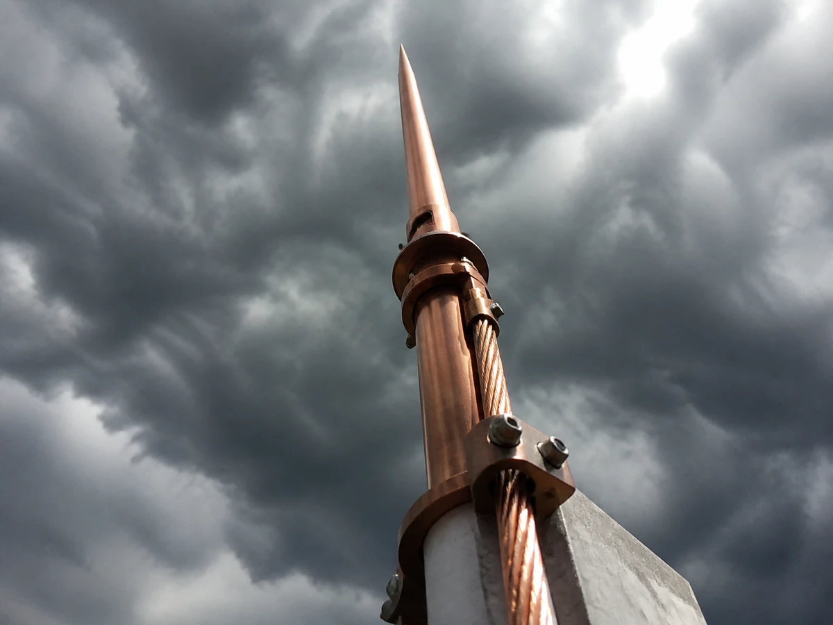
Risk assessment
Lightning risk assessment to IEC 62305-2 quantifies the probability and consequence of a lightning strike on the facility, which determines the protection level the design needs to achieve rather than defaulting to a blanket assumption. We assess structure type, occupancy, contents and the consequences of a strike to establish the required protection level, then size the air termination and down-conductor network to match. The assessment is documented so the protection level chosen can be justified to a client or auditor.
Air termination & down conductors
Air termination design — rods, mesh or catenary wires — uses the rolling sphere or mesh method appropriate to the structure's protection level, positioned to cover equipment and structures without unnecessary redundancy. Down conductors are routed to provide multiple, well-distributed paths to the earth-termination system, sized and spaced per IEC 62305-3. We coordinate air termination and down-conductor routing with the structural and architectural design so protection doesn't conflict with the building's actual geometry.
Surge protection (SPD)
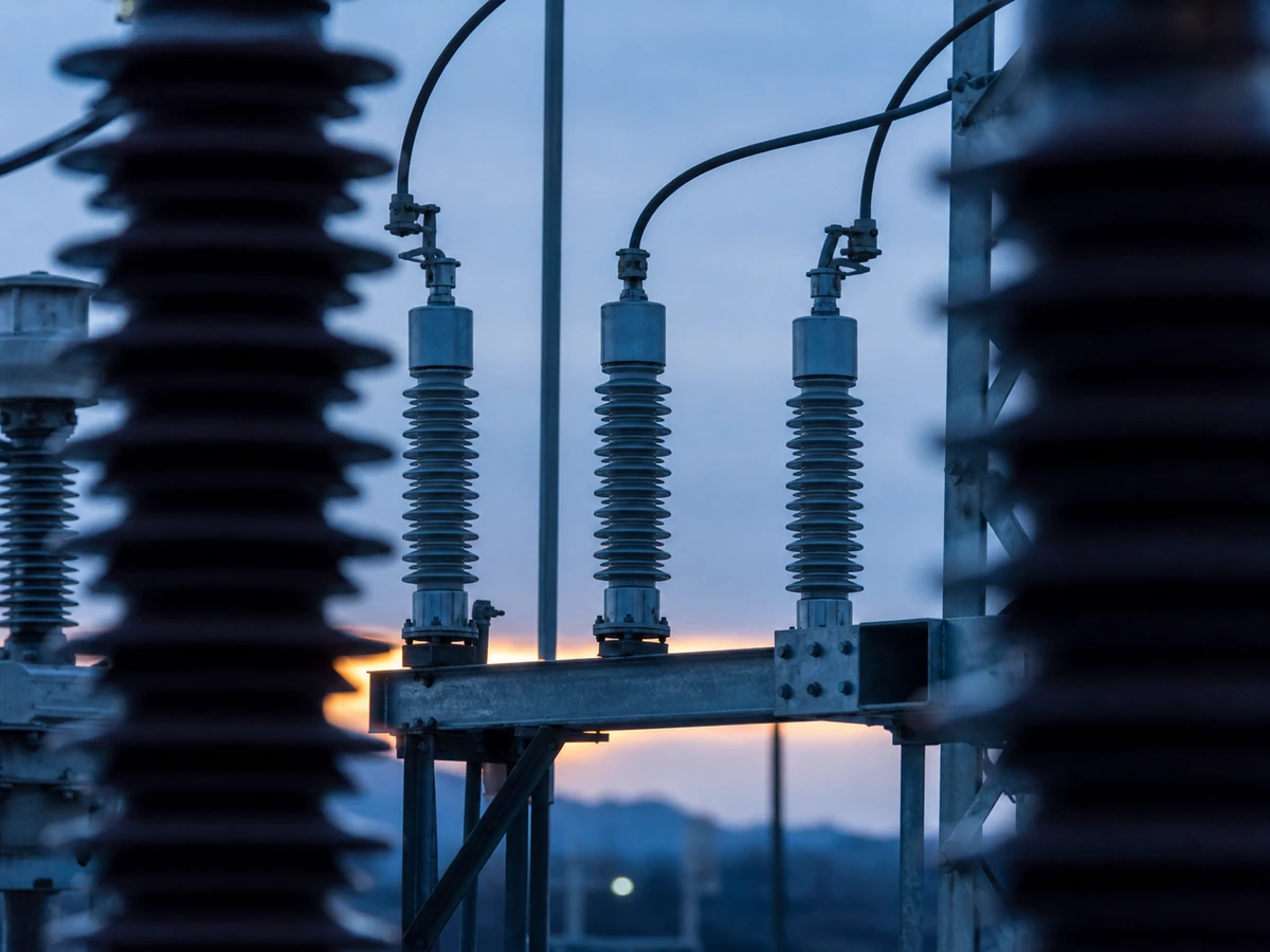
Surge protective devices are specified and coordinated across power and signal circuits to limit transient overvoltages reaching sensitive equipment, following the SPD zone concept so devices at each boundary are correctly rated relative to each other. We select SPD type and rating based on the exposure at each location, coordinate energy let-through between cascaded devices, and specify installation requirements — lead length, earthing — that determine whether the SPD performs as rated or not.
Standards & compliance
Lightning and surge protection design is delivered against IEC 62305 (or the regional equivalent the project requires), with the risk assessment, protection measures and SPD coordination documented in a compliance package suitable for client or authority review. We track which standard edition and national annexes apply to a given project, since requirements can vary by jurisdiction, and flag anywhere the client's own standard exceeds the baseline code so the design meets the more stringent requirement.
Have a scope in this area?
Share your requirements and we'll respond with a defined scope, programme and fixed fee — typically within two working days.
Request a proposal